Injector Characterization: Prior to 1997
For experiments before 1997, three injector tips with an off-axis nozzle were used, as shown in Fig. 2.4.3.1. These nozzles are denoted as xxx-s in the ECN database to indicate a non-axial, side holed injector. The spray remained directed into the center of the chamber, however. The nozzle tip sizes and coefficients are listed in Table 2.4.3.1, The coefficients given in Table 2.4.3.1 are based on the minimum diameter at the inlet for consistency with Table 2.4.3.1, unlike SAE 960034, which based coefficients on the orifices were slightly tapered with the diameter increasing by 4-6% from inlet to outlet.
Table 2.4.3.1 Injector tip parameters for off-axis nozzles.
| Orifice Diameter |
Discharge Coefficient |
Area-Contraction Coefficient |
Length-to- Diameter |
|---|---|---|---|
| d | Cd | Ca | L/d |
| [mm] | |||
| 0.185 | 0.64 | 0.93 | 5.4 |
| 0.241 | 0.71 | 0.92 | 4.2 |
| 0.330 | 0.66 | 0.89 | 3.0 |
FUEL INJECTION SYSTEM – The fuel injection system consists of a high-pressure liquid pump, accumulators, and an injector. The fuel injector was an electronically controlled, common-rail, solenoid-activated injector designed by Diesel Technology Corporation. It was placed in the left injector port (as shown in Fig. 2.1.2.1) with a single hole orifice oriented to inject fuel through the center of the chamber. Schematics of the injector and injector tip are shown in Fig. 2.4.3.1. The main features of the injector are the solenoid, the control needle, the main needle, and the fuel supply and return lines.
The enlargement on the top left in Fig. 2.4.3.1 can be used to describe the operation of the injector. Activation of the solenoid lifts the control needle, opening orifice A directly above the main needle. This action allows fuel flow from the supply line through orifice B into the small chamber above the main needle, then through orifice A to the return line. Since orifice B is smaller than A, the pressure in the small chamber is much less than the line pressure, creating a force imbalance that unseats the main needle and starts the injection. When the solenoid is deactivated a closure spring reseats the control needle. The pressure in the chamber above the control needle returns to the fuel supply pressure causing the main needle to reseat, ending injection.
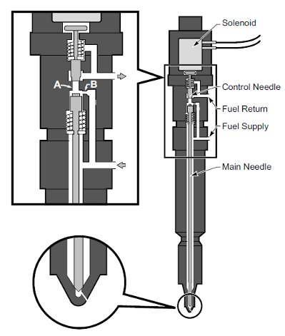
Figure 2.4.3.1 Schematics of the common-rail fuel injector and injector tip with 34° off-axis orifice.
Fuel is supplied to the injector from an accumulator located immediately upstream of the injector. The accumulator was sized to limit the pressure loss during injection to less than 2% for injections of up to 100 mg of fuel. The accumulator can be pressurized to 350 MPa by a high-pressure liquid pump; however, pressures were limited to less than 180 MPa by the injector design. The fuel pressure during injection was measured with a Kistler model 607L piezoelectric pressure transducer coupled to a Kistler model 504E charge amplifier with a 60 kHz low pass filter. The transducer was located between the injector and the accumulator. Since the tip orifice area is the most significant flow restriction between the accumulator and the injector tip (by an area ratio of 30:1 for the largest orifice diameter used), the pressure measured at this location is equal to the tip pressure. The pressure transducer was calibrated to the full pressure of the experiments against a reference transducer with an NBS traceable calibration. Calibrations were done with the transducer mounted in place at the operating temperature of the experiment. The accuracy of the calibration is 1%.
Fuel injection timing was measured optically via a photointerrupt technique. During injection, the fuel spray blocked a laser beam directed over the injector orifice and onto a photodiode. The signal generated by the photodiode allowed the detection of the start and end of injection.