Injector Characterization: 1997 to 2007
A common-rail fuel injector with a single, non-hydroground, axial hole was used for the experiments. These nozzles are denoted xxx-a in the ECN database to indicate an axial hole. The fuel injector was a prototype, electronically controlled, common-rail, solenoid-activated injector designed by Diesel Technology Corporation. (Schematic of the injector, Fig. 2.4.2.2). Fuel is supplied to the injector from an accumulator located immediately upstream of the injector. The accumulator was sized to limit the pressure loss during injection to less than 2% for injections of up to 100 mg of fuel.
Several types of injector tips were used. For experiments after 1997, cylindrically-shaped, on-axis injector tips were used as depicted in Fig. 2.4.2.1.
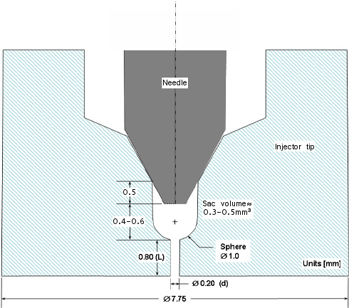
Figure 2.4.2.1
Important characteristics of the orifices used in the experiments are listed in Table 2.4.2.1. Values given in the table for each orifice are the nominal diameter (d), the discharge coefficient (Cd), the area-contraction coefficient (Ca) for two injection pressure differences across the orifice (72 and 138 MPa), and the length-to-diameter ratio (L/d). All the orifices had sharp-edged inlets and outlets and no hydro-grinding was performed. The shape of the orifices were captured using silicone molds that were made for the nozzles. Images for some of these molds can be found using the data search utility. Diameters listed in Table 5.1 are based on the minimum diameter. The sac-volume dimensions were preserved as orifice size or L/d ratio were varied (i.e., the dimension L was changed). Figure 2.4.2.1 shows a sample orifice with an L/d ratio of 4.
Table 2.4.2.1 Injector tip parameters for cylindrically-shaped tips used from 1997 to 2007.
| Orifice
Diameter |
Discharge
Coefficient |
Area-Contraction
Coefficient |
Length-to-
Diameter |
|
|---|---|---|---|---|
| d | Cd | Ca | Ca | L/d |
| (mm) | (72 MPa) | (138 MPa) | ||
| 0.100 | 0.80 | 0.91 | 0.86 | 4.0 |
| 0.180 | 0.77 | 0.85 | 0.82 | 4.2 |
| 0.251 | 0.79 | 0.88 | 0.79 | 2.2 |
| 0.246 | 0.78 | 0.89 | 0.81 | 4.2 |
| 0.267 | 0.77 | 0.89 | 0.82 | 8.0 |
| 0.363 | 0.81 | – | 0.85 | 4.1 |
| 0.498 | 0.84 | 0.94 | 0.88 | 4.3 |
The injector tip is a 7.75 mm cylinder with a flat tip (Fig. 2.4.2.2). The tip protrudes approximately 5 mm into the chamber. This dimension changes slightly (less than 1 mm) if different tips are used. Experiments were performed with an exposed, uncooled tip (fuel temperature approximately 436 K) or with a 25 mm diameter ceramic body surrounding the injector tip for fuel-temperature-controlled experiments (i.e. 373 K to 436 K). The ceramic cooling body protrudes the same distance into the vessel as the injector tip.
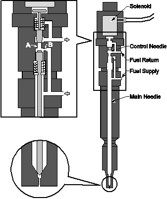
Figure 2.4.2.2