Modeling Standards and Recommendations
Modeling standards for Spray G have been identified to describe liquid and vapor penetrations and other parameters in a consistent way. CFD Groups (Argonne National Lab (ANL), Politecnico di Milano (Polimi), University of Wisconsin – Madison (UW)) for ECN3 have picked metrics that will be used for comparison of modeling results. CFD activities should be performed and post-processed according the following standard definitions and recommendations. Please also see Spray G under ECN3 proceedings for more information.
- Liquid Penetration
- % Liquid volume fraction threshold
- Vapor Penetration
- % Mixture fraction threshold
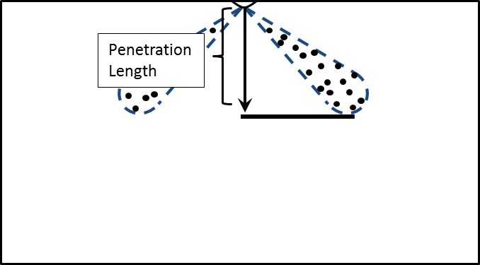
Liquid and vapor penetrations measured along the injector axis, see below figure 3. Zero point is set at the injector tip.
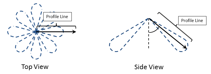
Mixture fraction and sauter mean diameter (SMD) profile locations are defined as below:
1. Spray Axis- Along center line of an individual jet (zero at injection location, positive towards spray tip), figure 4.
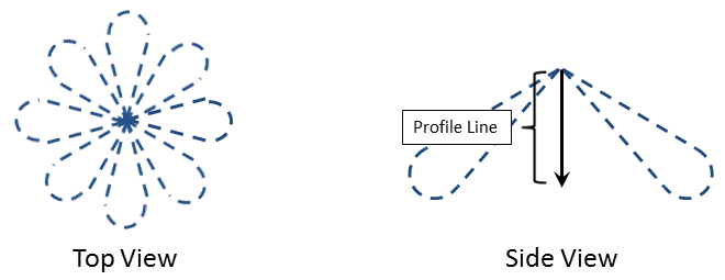
- Plane normal to injector axis
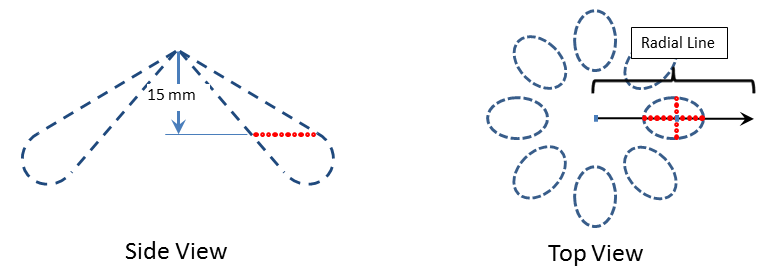
- Located 15 mm downstream of injector tip measured along injector axis
- Radial cross-section: along a radial line through the spray axis center point (zero at injector axis, positive outward), figure 6.
- Transverse cross-section: across the spray perpendicular to the radial line (zero at spray center point and positive direction clockwise as viewed from injector), figure 7
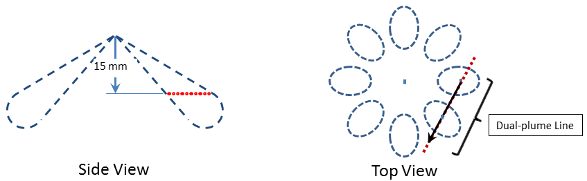
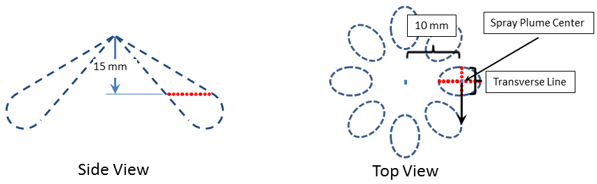 Figure 7: Transverse cross-section4. Dual-plume cross-section (this is for understanding plume-to-plume interaction), figure 8.
- Taken along a line connecting the center-points of two neighboring spray plumes
- Zero at center of counter-clockwise-most (as viewed from injector) plume
- Positive towards second plume (clockwise as viewed from injector)