Cross-Optical, Cube-Shaped Vessel
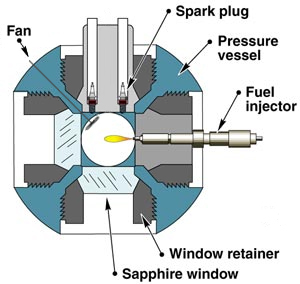
Figure 2.1.1.1
Figure 2.1.1.1 shows a schematic cross-section of the combustion vessel. The vessel has a cubical-shaped combustion chamber. The characteristic dimension of the cube is 108 mm. Each side of the combustion chamber has a round port with a diameter of 105 mm. The fuel injector is located in one side port using a metal insert that forms the right wall of the combustion chamber. Two spark plugs and a mixing fan are mounted in another metal insert that forms the top wall of the chamber. Optical access is provided by four sapphire windows with clear apertures of 102 mm located in the other four ports. For wall heat transfer modeling purposes, the steel vessel and metal inserts for the injector and spark plugs are made of 4340 steel.
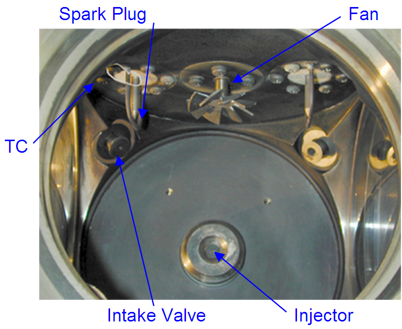
Figure 2.1.1.2
A picture of the inside of the combustion vessel is shown in Fig. 2.1.1.2. Visible objects include the spark plugs, mixing fan, injector, intake valves, and a beaded thermocouple. Two spark plugs are used to produce consistent combustion in the high-density, fuel-lean environment. The spark gap located is 16.5 mm below the vessel top and at a radius of 31.8 mm relative to center of vessel. Electrode diameter is 3.2 mm. Ground strap diameter is 1.6 mm. Ground strap leads (in-line with the electrode) are separated by 21 mm.
The mixing fan at the center is operated at 8000 rpm to ensure uniform ambient conditions at the time of injection. The bottom of the fan is approximately 15 mm below the vessel top. The outer diameter of the fan is 25 mm. There are eight fan blades, oriented at a 30 degree angle relative to horizontal, attached to a 7 mm disk at the center. Fan blades are 0.85 mm thick.
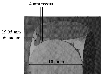
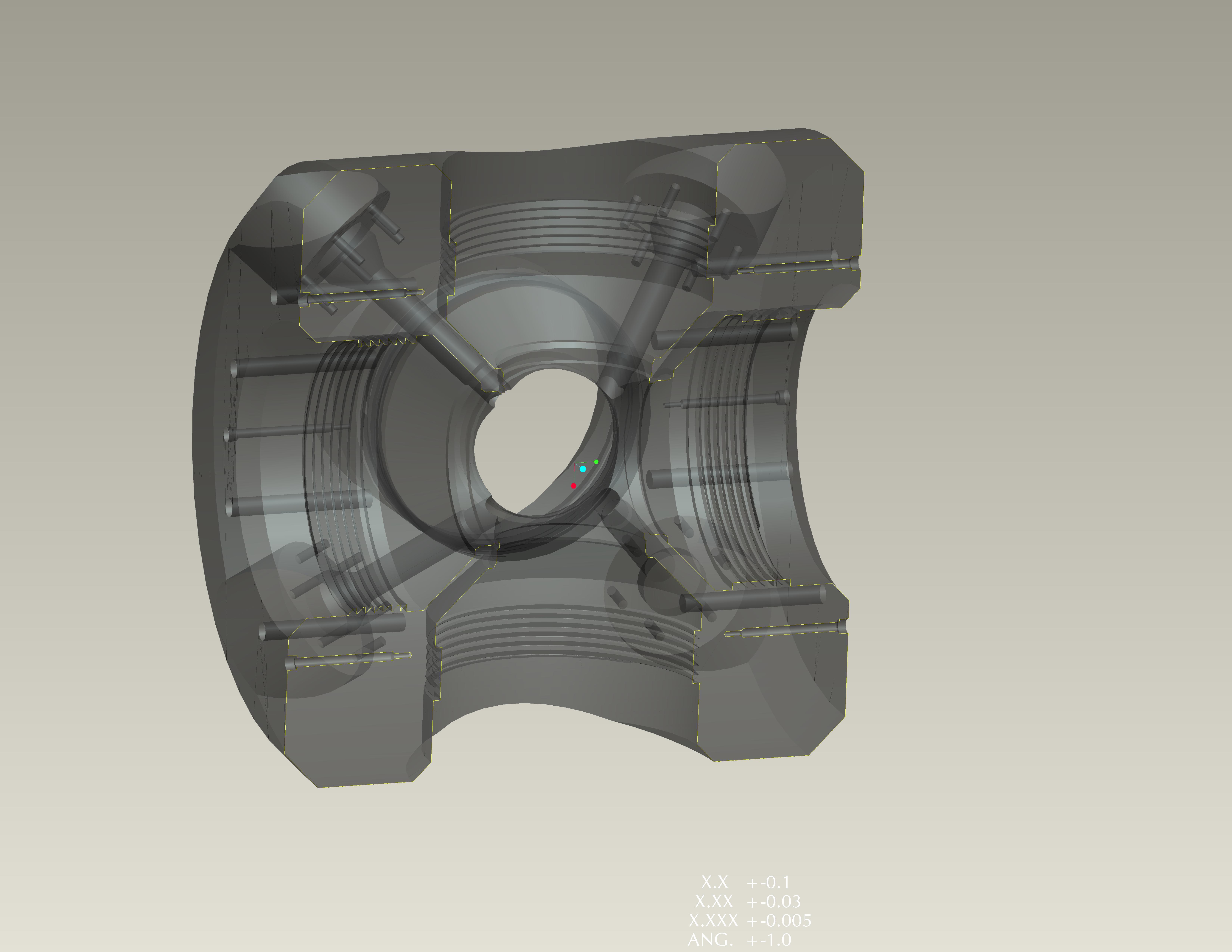
Figure 2.1.1.3
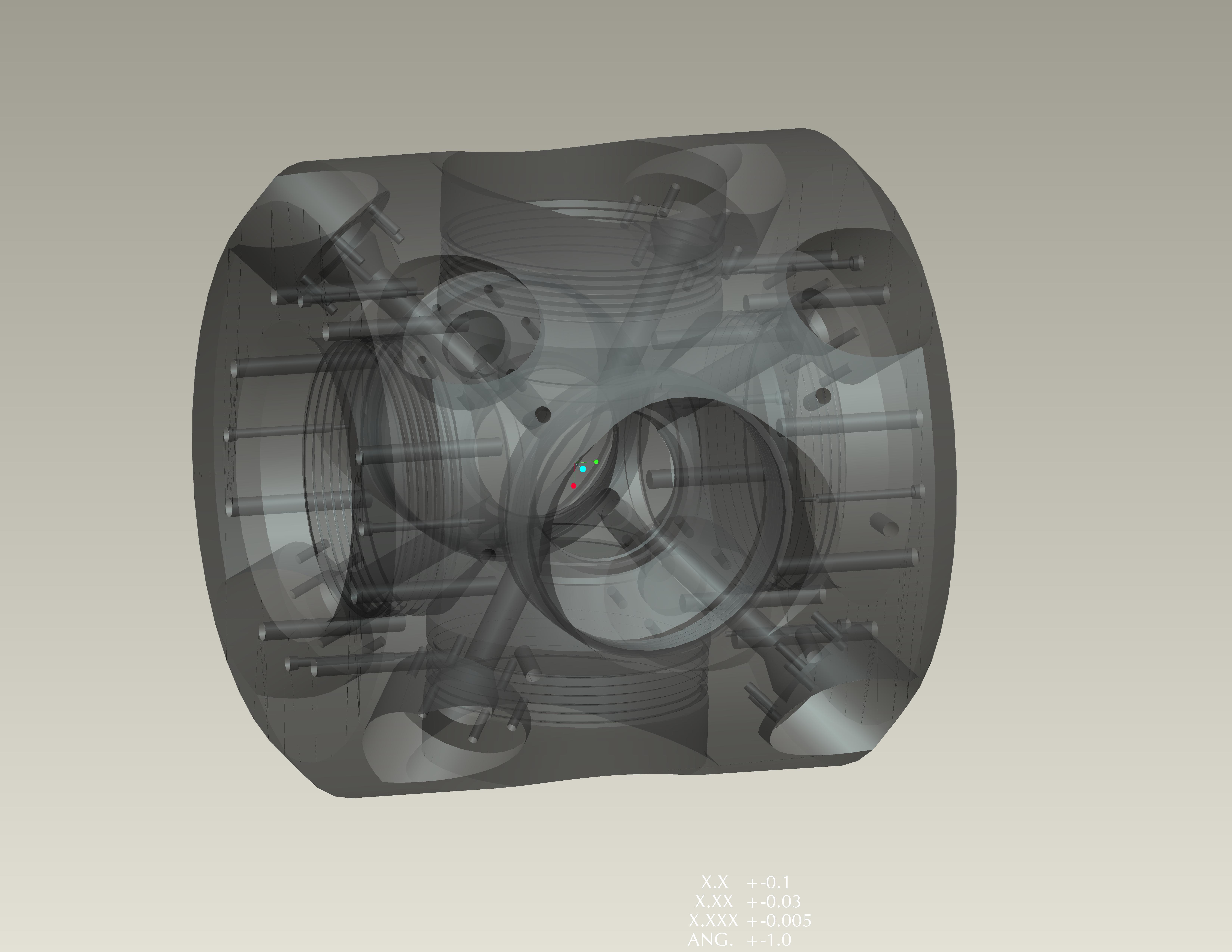
Intake and exhaust valves, or instruments such as pressure transducers or thermocouple inputs, are mounted at the corners of the cubical-shaped combustion chamber. Figure 2.1.1.2 and the solid model of the chamber volume (Fig. 2.1.1.3) show that the edge of the cube is an extension of the 105 mm cylindrical ports with a 19.05 mm port hole going exactly through the corner of the cube. Closed valves are recessed a depth of 4 mm from the highest part of the extended cylinder ports. Note that the windows are recessed some from the 105 mm bored port diameter, so that the effective cube dimension is 108 mm.
The injector protrudes into the vessel consequently affecting the vessel geometry. For more details on the injectors characteristics please visit the injector characterization web pages.
This combustion vessel has been operational at Sandia since 1997 (Siebers, 1998) and is currently in use. Prior to this time, a disk-shaped combustion vessel was used (Naber, 1996). The disk-shaped combustion will not be described here but the ambient conditions generated were similar to the current facility and data obtained in the disk-shaped chamber (jet penetration) is included in the ECN database.
Half chamber view