Bosch donated five nominally identical single-hole injectors for “Spray A” research. All ambient and injector operating conditions for Spray A research are given in detail. The specifications for the injector and nozzle are as follows:
| Specifications for Spray A injectors of the Engine Combustion Network | |
| Common rail fuel injector | Bosch solenoid-activated, generation 2.4 |
| Fuel injector nominal nozzle outlet diameter | 0.090 mm |
| Nozzle K factor | K = (dinlet – doutlet)/10 [use μm] = 1.5 |
| Nozzle shaping | Smoothed by hydro-erosion |
| Mini-sac volume | 0.2 mm3 |
| Discharge coefficient at 10 MPa pressure drop | Cd = 0.86 (room temperature using diesel fuel) |
| Number of holes | 1 (single hole) |
| Orifice orientation | Axial (0° full included angle) |
Note that the actual nozzle diameter and discharge and area-contraction coefficients measured at the Spray A conditions are significantly different than the nominal values given in the table.
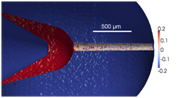
The table below provides measured nozzle geometry information obtained via various techniques as discussed in Kastengren, 2012. Silicone mold analysis has also been performed for nozzle 675. Orifice exit boundaries (X-Y profiles measured via optical microscopy) are provided in the table as text files (*.txt), centered on the axis of the injector to highlight the offset of the orifice at the outlet. Equivalent diameter along the axis of the orifice is given based on tomography or phase-contrast analysis. To remove artifacts of inlet rounding, we fit the equivalent diameter from 10-80% of the hole length and then extrapolate this fit to the inlet and exit of the nozzle to determine the K factor.
Optical microscopy, x-ray tomography, and x-ray phase contrast derived data
 |
 |
 |
|
| Optical microscopy | X-ray tomography surface | X-ray phase contrast projection |
| Injector Serial # | Exit diameter [μm] | Exit boundary [μm] | θ [deg.] | Surface file .stl | Exit offset [μm] | Axial diameter profile [mm] | K-factor | Inlet radius [μm] | Axial diameter profile [μm] | K-factor |
| 210370 | 90.8 | B1 | -90 | stl | 50 | P1 | 1.5 | 23 | – | – |
| 210675 | 89.4 | B1 | 9 | stl*; stl | 53 | P1 | 1.3 | 25 | – | – |
| 210677 | 83.7 | B1 | 32 | stl | 37 | P1 | 1.8 | 20 | P2 | 1.8 |
| 210678 | 88.6 | B1 | 36 | stl | 39 | P1 | 1.8 | 19 | P2 | 1.7 |
| 210679 | 84.1 | B1 | -22 | stl | 22 | P1 | 1.8 | 17 | P2 | 1.8 |
*Note 210675 tomography has been updated based on high-resolution x-ray tomography performed at CNRS, France by Ali Chirazi. The raw data was smoothed to create the stl file given, which was recommended for computational grid generation for ECN3.
Below is a schematic of the definition used for the hole orientation. The orifice exit is located on the origin of the cartesian coordinates system used (X, Y, Z). The orientation angle θ together with the exit offset represent the location of the orifice with respect to the axis of the injector body and the fuel tube. Note that the orientation angle is also expressed as φ, the angle used by the manufacturer. However, φ is referenced with two pins to hold the nozzle in position with respect to the injector body, which are not visible from outside (without unmounting the nozzle). For that reason, θ is defined as the angle between the fuel tube and the actual orifice in the counter clockwise direction when facing the injector tip. The offset presented in the table above corresponds to the distance between the axis of the injector and the axis of the orifice at the exit.
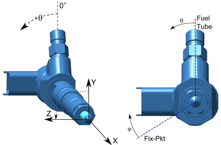
Fig. 6.3.1. Schematical definition for the orientation of the orifices for Spray A (axial single-hole nozzle).
Stereo lithography files (.stl) derived from x-ray tomography are provided for each nozzle in the table according to the injector orientation convention, except the axial distance in these files is the z coordinate. For modeling these nozzles, be aware that the actual nozzle surface is not portrayed perfectly in these stl files because of measurement artifacts, as discussed by Kastengren, 2012. Efforts are currently underway to produce more refined surface files. An idealized hexahedral mesh has also been generated for nozzle 675.