Spray G meshes and surface files have been prepared to facilitate internal flow and external spray CFD modeling. The tables below list Gen. 1 nominal, specified geometries, along with other “educated” geometries that reflects features from the measured geometry, while also attempting to remove known uncertainties in the measured geometry. The J2715 standard orientation convention has been used by the ECN Spray G community with z = 0, y = 0, x = 0 defined as the tip of the nozzle. In the spirit of the ECN, we encourage use of these meshes/geometries for open scientific exchange on the topic of gasoline spray modeling and ask that you notify Lyle Pickett if you use these meshes. Delphi has provided access to the specified geometries and several of the meshes have been prepared for the ECN and made available by GridPro.
Spray G specified nozzle geometry
| Number of holes | 8 |
| Spray Shape | circular |
| Bend Angle | 0° |
| L/D ratio | 1.4 |
| Hole shape | straight |
| Manufacturing | EDM |
| Flow rate | 15 cc/s @10 MPa |
| Fuel injector | Delphi solenoid-activated |
| Nozzle type | Valve-covered orifice (VCO) |
| Nozzle shape | Step hole |
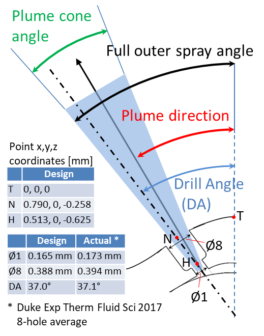
| Orifice diameter | 0.165 mm specification (0.170 mm measured) |
| Orifice length | 0.16-0.18 mm |
| Step diameter | 0.388 mm specification |
| Orifice drill angle | 37° relative to nozzle axis |
| Full outer spray angle | 80° |
Simplified/updated Spray G Geometry based upon Generation 3 measurements–to be used for ECN 7 (Generation 3.2)
| File Links | Description |
| https://anl.app.box.com/v/XRaySpray/folder/34814463018 | See this page for Generation 3.2 STL geometry files created from Argonne x-ray computed tomography measurements for injector #28, known as the Generation 3 geometry. View the README pdf file for information about the differing models. |
Spray G nozzle geometry based upon detailed Argonne x-ray computed tomography measurements (Generation 3)
| Solidworks CAD File was recommended for all ECN6 CFD simulations. | Original Argonne x-ray CT Measurements of Injector #28 | - | |
| File format | .SLDPRT (1.5 MB) | .STL (2.1 GB) | - |
| Description | CAD file was generated based upon analysis of Argonne x-ray geometry measurements. Raw geometry measurements were not yet suitable for surface file generation, and also lacked upstream features above the ball/pintle. README can be found here. | Please refer to README notes at the referenced links. Because of the complexity, this raw .STL is not recommended for ECN6 simulations. | - |
Spray G nozzle geometry based upon early measurements (Generation 2)
| Measured via x-ray tomography | Generation 2 Justification | OpenFOAM grid | |
| File format | .stl (112 MB) | .ppt (6.2 MB) | OpenFOAM grid package .7z (200 MB) |
| Description | Commercial x-ray tomography performed for injector #28. Shape of certain features is not resolved as the voxel resolution was 5.07 micrometers. Needle/pintle in the closed position. | Presentation details features in question and justification for decisions about meshing these features. | Mesh with 9 mm cap prepared and donated to the ECN by GridPro |
Spray G specified nozzle geometry (Generation 1)
| Nozzle and ball | Nozzle with 3mm cap | Nozzle with 9mm cap | OpenFOAM grid | |
| File format | .stl (1.3 MB) | .stl (1.3 MB) | .stl (1.6 MB) | OpenFOAM grid package .zip (50 MB) |
| Description | Specified nozzle and ball | Nozzle with 3 mm "cap" outside of nozzle, discussed at ECN3, topic 3.5. Needle/pintle is in the "open" position. | Nozzle with 9mm "cap" outside of the nozzle. Discussed at ECN3, topic 3.5. | Mesh prepared and donated to the ECN by GridPro |