Five Spray D nozzles were manufactured to with hydro erosion and convergence to minimize cavitation while specified to have a similar flow number as Spray C. Specifications and actual values are given below, along with full 3D geometry and needle movement measurements:
| Specified and actual quantities for Spray D injectors of the ECN |
| Common rail fuel injector |
Bosch 3-22 |
| Number of holes |
1 (single hole) |
| Hole nominal diameter |
0.186 mm |
| Hole outlet diameter (actual) |
0.189 mm |
| Hole minimum diameter (actual) |
0.188 mm |
| Nozzle K factor |
K=1.5 |
| Nozzle shaping or hydroerosion |
seeking Cd = 0.86 |
| Mini-sac volume (not including hole) |
0.65 mm 3 |
| Flow with 10 MPa pressure drop |
228 cc/min |
| Hole angular position |
axial |
Nozzle geometry measurements have been made using x-ray computed tomography (CT) and optical microscopy. From these measurements, various surface (STL) files have been prepared, particularly for Injector 209134, and are available to use for CFD. The “Generation 2” measurements performed at Argonne National Laboratory at the Advanced Photon Source have better measurement resolution than previous commercial x-ray CT, and are therefore recommended/preferred. The original measurement and derived STL files are listed in Tables below.
Generation 2 x-ray CT measurements for Injector 209134:
|
| Measurements were performed in 2016 by Argonne National Laboratory offering resolution approaching 1 micrometer. Please find description and access to original STL datafiles and cite Matusik et al. |
| STL created for CFD |
Description |
Citation |
File size |
| Battistoni smoothed 2018 |
High detail on the original 750 MB file on the outside of the nozzle or in the sac region is smoothed, as this has no bearing on internal flow. Internal nozzle details are retained. Includes needle and some upstream downstream regions for CFD. Recommended for ECN7. |
ECN6 proceedings |
66 MB |
| Yasutomi smoothed 2019 |
Economical geometry coarsened slightly in hole. Not as capable for representing surface roughness features, but accurate for overall geometry. |
Yasutomi 2019 |
4 MB |
| Wireframe |
|
|
|
| Hole and sac wire frame |
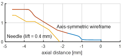
Axis-symmetric “wire frame” derived from Gen 2 geometry for simplified calculations. Radial distance is the “effective” radius for the flow area, rather than circle fits applied by Matusik et al. |
ECN6.14 LM Pickett, Sandia |
4 KB |
| needle geometry |
Axis-symmetric “wire frame” for needle radius in a lifted state 0.4 mm from seat. |
|
1 KB |
Needle movement measurements for Injector 209134:
|
| Measurements were performed in 2017 by Argonne National Laboratory using phase-contrast imaging. Please find description, access to original data, and citation. One column of data is needle movement corrected for needle elasticity (see Yasutomi 2019 ), which is recommended for use at ECN7. |
| Needle movement |
Injector temperature |
Fuel pressure |
Gas pressure |
Electronic command duration |
Hydraulic injection duration |
| D134 Needle Movement |
24 C |
1500 bar |
20 bar |
0.795 ms |
2.45 ms |
| Generation 1 x-ray CT measurements for Injector 209134: |
| Description: 3D volumetric slices and surface files were provided directly from North Star Imaging after measurements were performed in 2014. Sandia National Laboratories performed analysis and created an axis-symmetric wireframe for the needle and hole as given at the right of the table. Please reference Sandia and this website page for use of this data. |
 |
 |
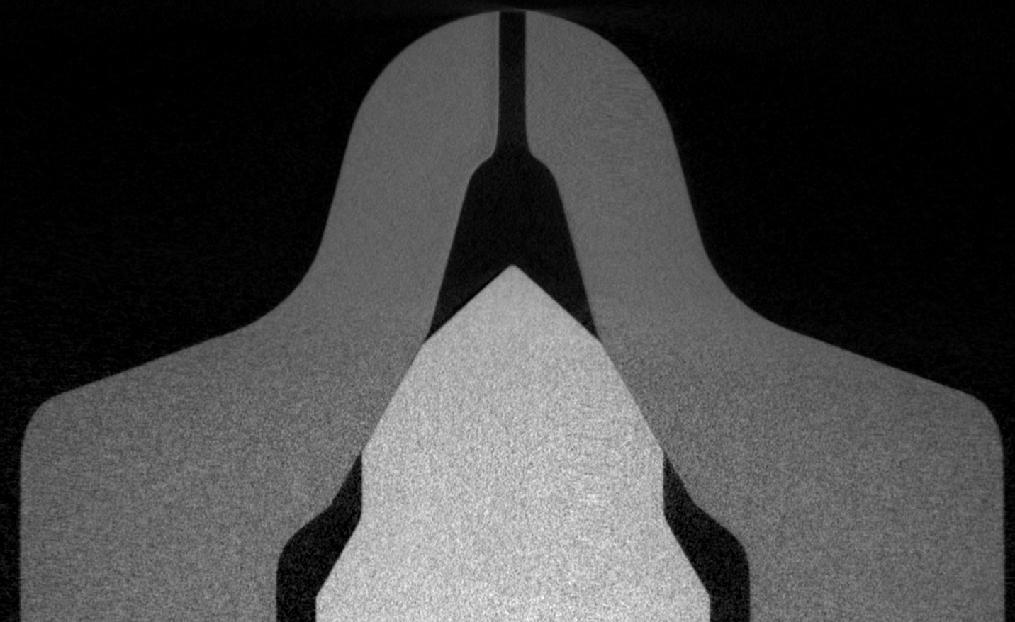
| Slice from 3D CT at central cross-section of injector, with 5.05 μm per pixel. |
2D axis-symmetric wireframe |
| stl (177 MB) |
wire frame hole and sac radius vs x (.csv) |
| download image |
wire frame needle radius vs x (.csv) with 0.4 mm lift |
| Optical microscopy of nozzle 209134 exit |
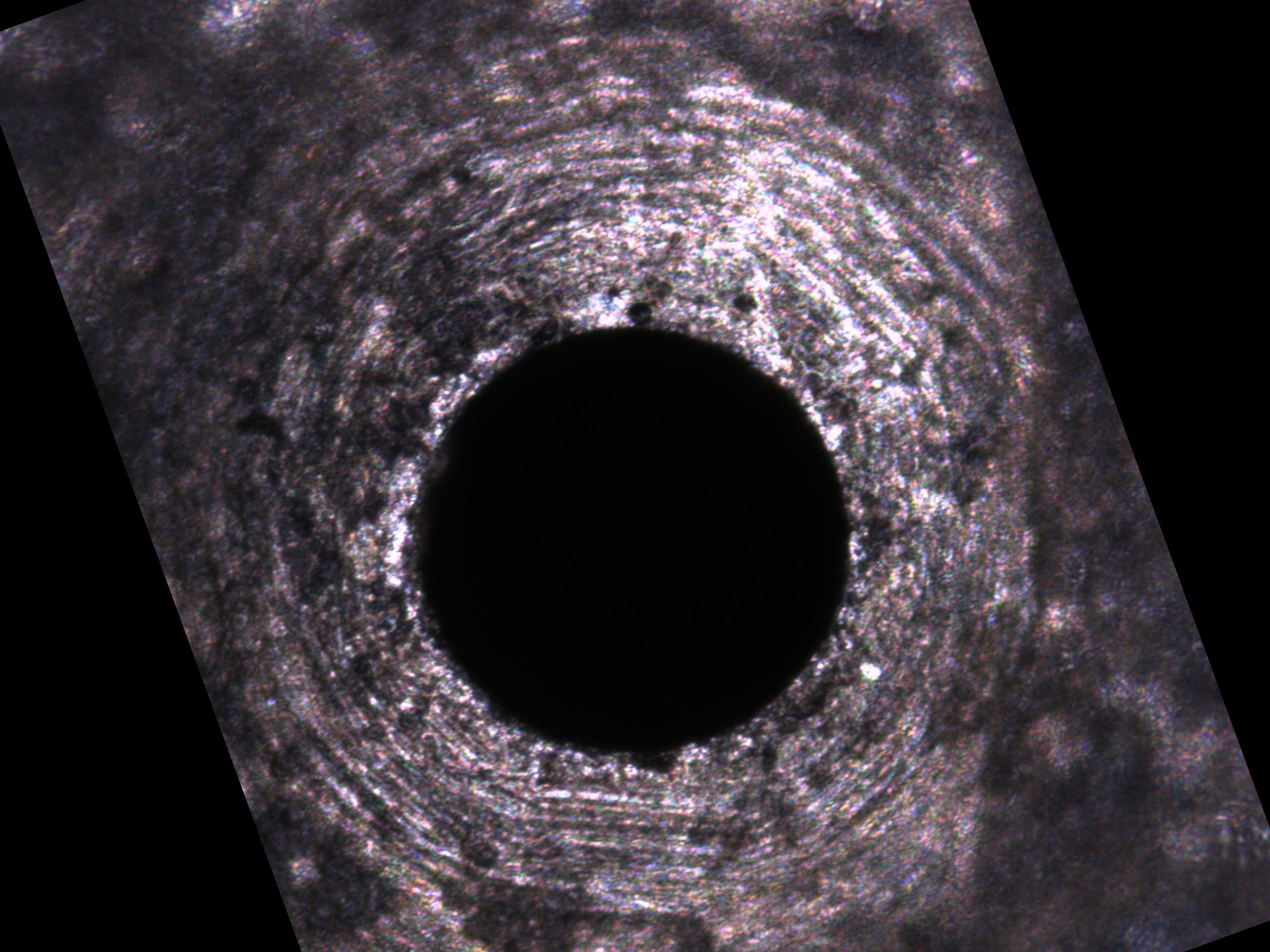
| Description: Microscopic imaging performed at Sandia National Laboratories with 0.2155 μm per pixel. Nozzle exit cleaned using compressed air. Analysis shows an exit area corresponding to an effective diameter of 188 μm. Cite this website page to reference this data. |
| Image |
Other details |
| nozzle exit |
Injector is oriented with fuel tube in up position per ECN convention. |
Other related links: