Combustion Vessel Geometry: 2009 to Present
Cross-Optical, Cube-Shaped Vessel
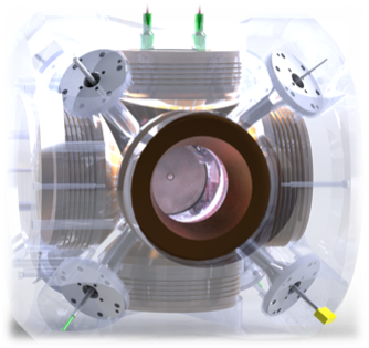
Figure 1
This version of the vessel has a fan in the top-left corner port that operates at approximately 1000 rpm. The fan was moved from the center port and the fan speed lowered to decrease optical interference and to reduce thermal boundary layer structure on the windows. The measured temperature distribution for the 1000-rpm chamber shows a uniform core temperature, but there is more vertical temperature stratification compared to that with 8000 rpm (bottom figure).
Another difference compared to earlier versions of the chamber is that the injector port protrudes in a slightly conical fashion. Other than these changes, the vessel dimensions and electrode specifications are the same as the ones stated on the Combustion Vessel Geometry: 1997 to 2009 page.
Please use the following link to download the CAD geometry in STL format. The real geometry is also available in surface.dat format, which can be read directly by CONVERGE. Figure 2 below illustrates three plans: XY in blue at Y= 0 mm, YZ in red at X= 39.5 mm, and XZ in black at X = 0 mm. The conical shape induced by the injector port can be observed on the XZ and YZ plan as well as the spark plugs on the top of YZ plan.
For single-hole injector we advocate to use cartesian coordinate system, where the injector’s coordinates are [0; 0; 0]. To avoid parcels being injected outside of the domain we recommend to shift the nozzle location by 1 µm downstream the injector, the nozzle coordinates are therefore [1e-6; 0; 0].
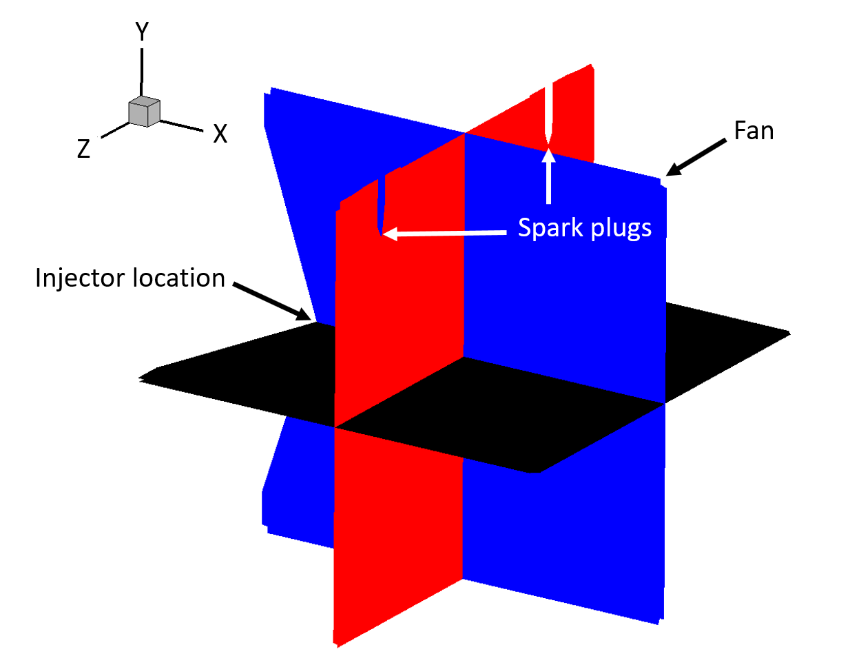
Figure 2