Combustion Vessel Geometry: Prior to 1997
Line-of-Sight, Disk-Shaped Vessel
The experimental apparatus consists of a constant-volume combustion vessel, a high-pressure fuel injection system, a schlieren imaging system, and data acquisition and control systems. The apparatus is located in a high pressure test cell and is controlled and operated remotely by a computer.
COMBUSTION VESSEL – Figure 2.1.3.1 shows schematic cross-sections of the constant-volume combustion vessel. The vessel has a disk-shaped combustion chamber 114.3 mm in diameter and 28.6 mm in width. Sapphire windows on either side permit full line-of-sight optical access through the vessel. The walls of the vessel can be electrically heated to temperatures up to 525 K to reproduce engine wall temperatures and prevent water condensation on the window surfaces. Around the circumference of the vessel are five access ports and two injector ports. This vessel is similar to one used previously for diesel combustion studies (Siebers, 1985), except that the new vessel is designed for significantly higher pressures (up to 35 MPa).
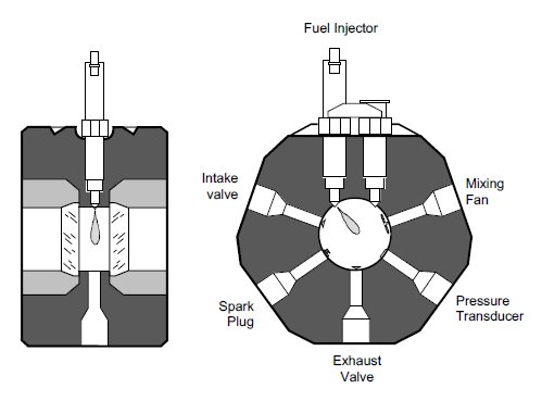
Mounted in the five access ports in the positions shown in Fig. 2.1.3.1 are: two solenoid controlled air-operated valves, one for intake and the other for exhaust; a surface gap spark plug; a pressure transducer; and a mixing fan. (The functions of the spark and combustion vessel mixing fan are discussed in detail later.) The pressure transducer used was a Kistler model K- 6001 piezoelectric pressure transducer coupled to a Kistler model 504E charge amplifier with a 20 kHz low pass filter. A perforated metal thermal barrier covering the pressure transducer delayed the effects of the thermal pulses from combustion events on the pressure measurements for approximately two seconds. (A typical experiment discussed in the Experimental Procedure and Conditions Section required less than 1.5 seconds to complete.) The pressure transducer was routinely calibrated up to the full pressure of the experiments against a reference transducer with an NBS traceable calibration. The calibrations were conducted with the transducer mounted in place at the operating temperature of the experiment. The accuracy of the calibration is 1%.