“Spray B” is a three-hole Bosch injector with the same orifice specifications as Spray A. Five nominally identical 3-hole nozzles are used. The specifications are as follows:
| Specifications for Spray B injectors of the Engine Combustion Network | |
| Common rail fuel injector | Bosch solenoid-activated, generation 2.4 |
| Fuel injector nominal nozzle outlet diameter | 0.090 mm |
| Nozzle K factor | K = (dinlet – doutlet)/10 [use μm] = 1.5 |
| Nozzle shaping | Smoothed by hydro-erosion |
| Mini-sac volume | 0.2 mm3 |
| Discharge coefficient at 10 MPa pressure drop | Cd = 0.86 (room temperature using diesel fuel) |
| Number of holes | 3 |
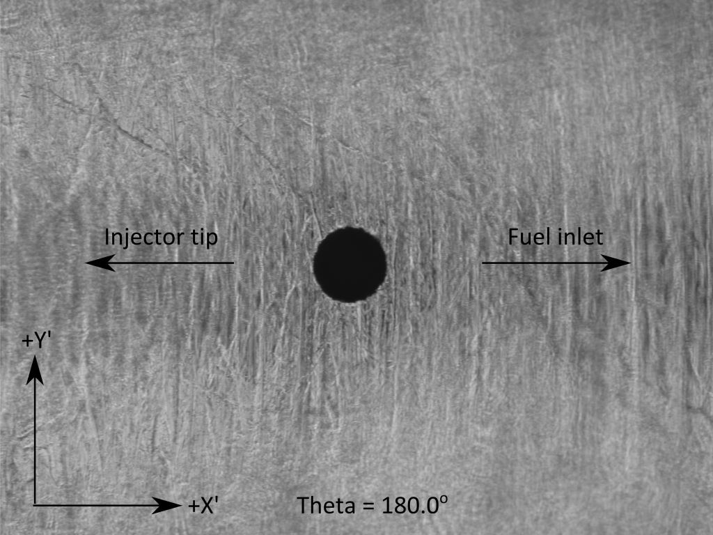
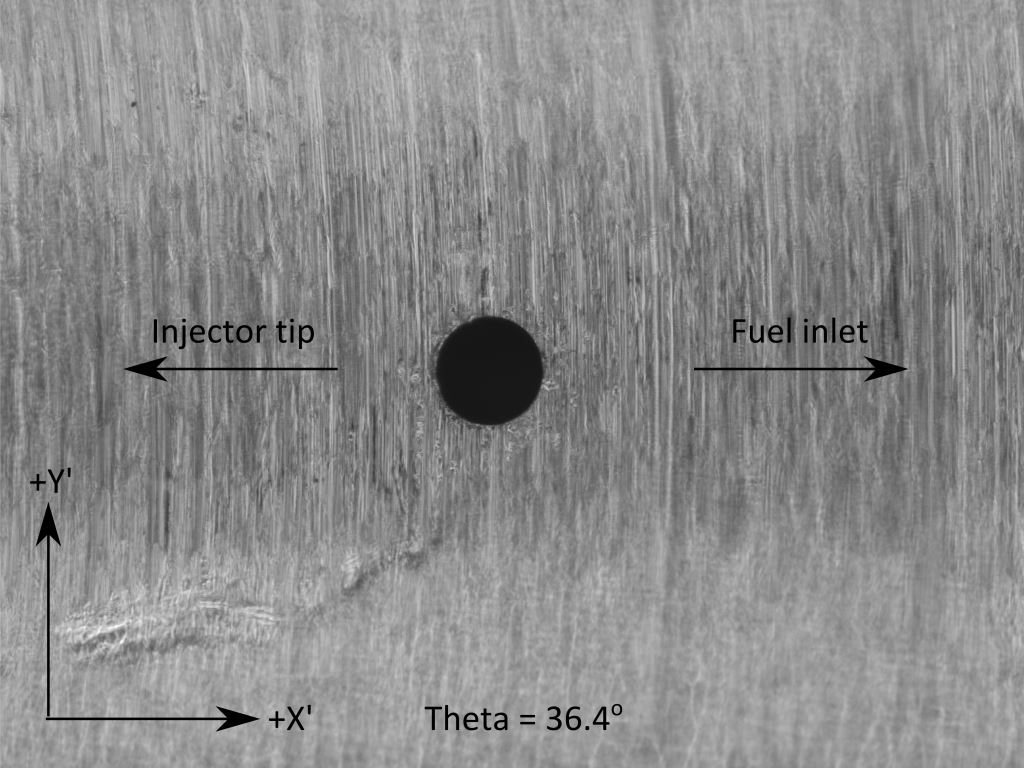
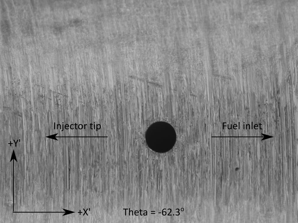
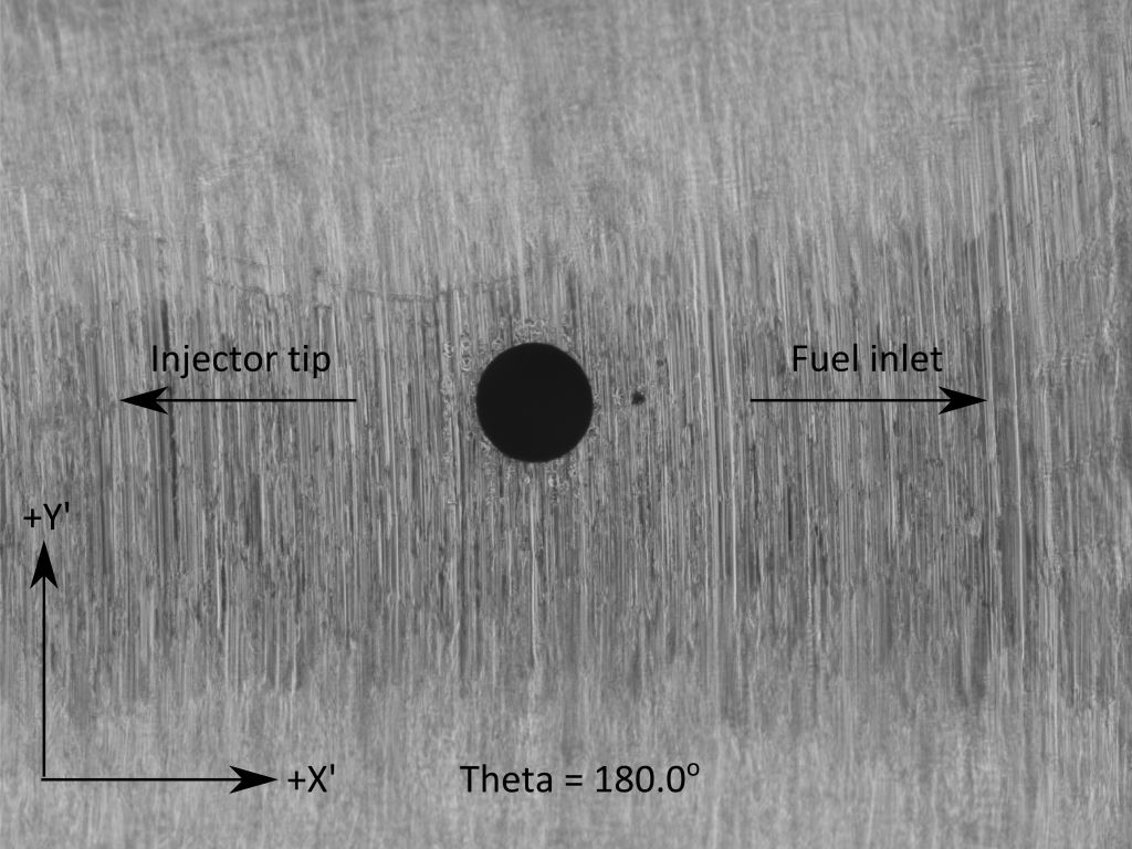
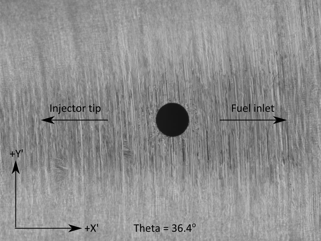
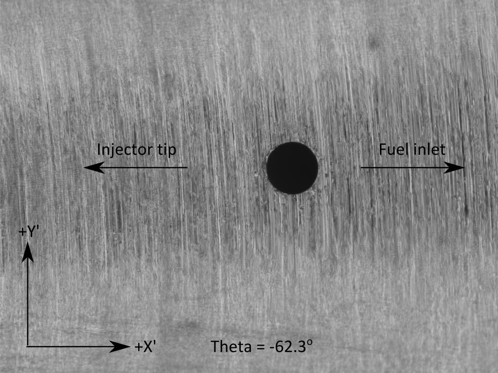
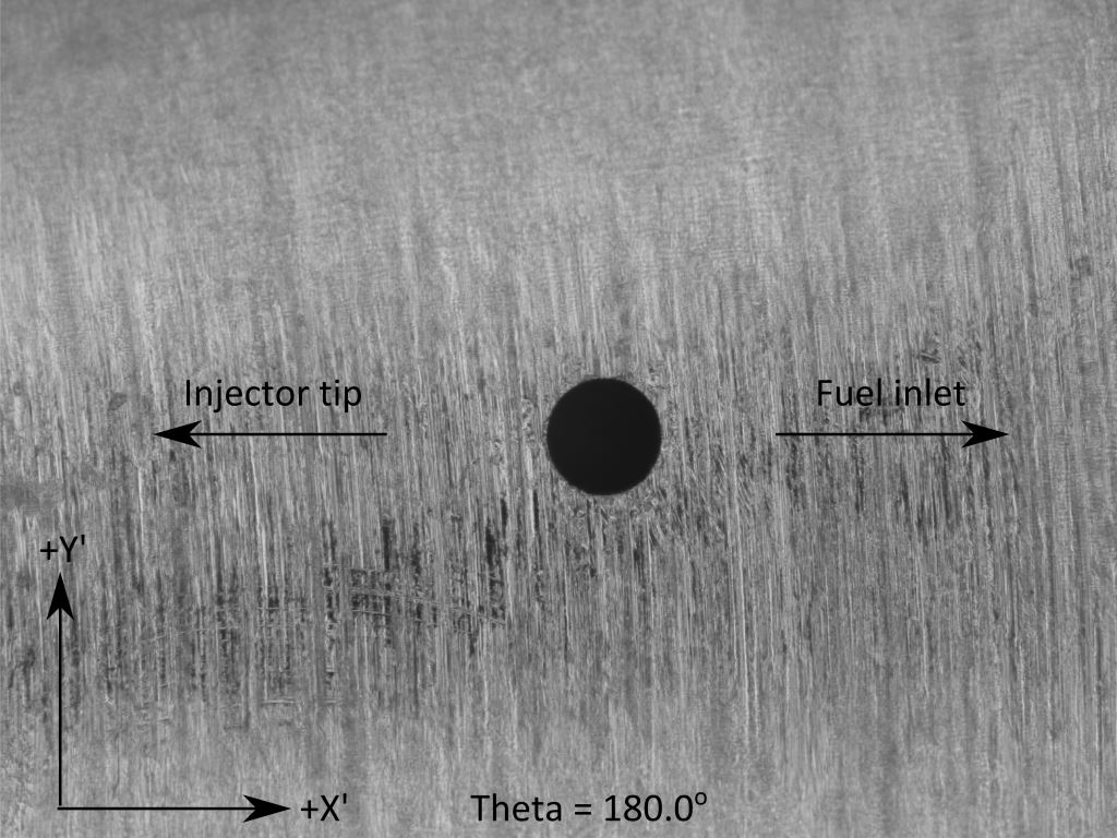
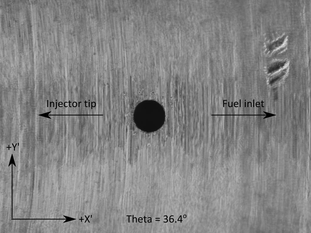
| Hole angular position | θ = 36.4°, -62.3° and 180° |
| Orifice orientation relative to injector axis | ψ = 72.5° (145° full included angle) |
The hole of main interest is the one drilled opposite to the fuel tube (Hole #3) . The nozzles have been designed so that the other sprays would not visually interfere with the spray of interest. Below is a schematic of the definition used for the hole orientation. The orientation angle θ represents the location of the orifice with respect to the axis of the fuel tube. The orientation angles given by the manufacturer are 36.4°, -62.3° and 180° for orifices 1, 2 and 3 respectively. Note that the orientation can also be expressed as φ, the angle used by the manufacturer with reference to two locator pins holding the nozzle in position with respect to the injector body. But these pins are not visible from outside (without unmounting the nozzle). For that reason, θ is defined as the angle between the fuel tube and the actual orifice in the counter clockwise direction when facing the injector tip.
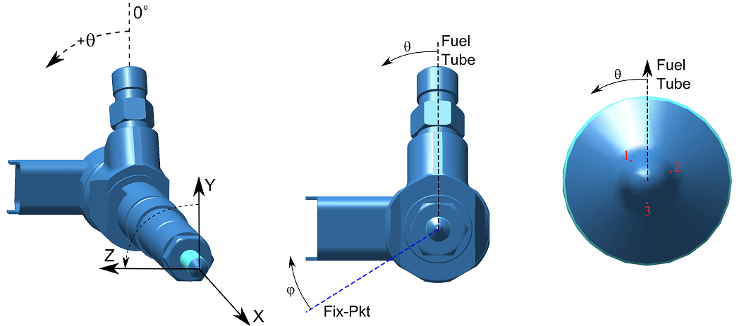
Fig. 6.4.1 Schematical definition for the orientation of the orifices for Spray B (145° included angle 3-hole nozzle). The hole of interest for Spray B is opposite to the fuel tube (hole #3).
Spray B geometry derived from x-ray tomography and optical microscopy
The table below shows measured nozzle geometry information obtained via various techniques as discussed in Kastengren, 2012. x-ray tomography measurements are courtesy of Tim Bazyn of Caterpillar (stl) and Peter Hutchins of Infineum Ltd (ESRF stl). Stereo lithography files derived from x-ray tomography are provided for each nozzle. For modeling these nozzles, be aware that the actual nozzle surface is not portrayed perfectly in all stl files because of measurement artifacts (see Kastengren, 2012). As such, only the high-resolution ESRF stl for injector 211201 is recommended for internal flow modeling for ECN3.
| Injector Serial # |  Surface file .stl Surface file .stl |
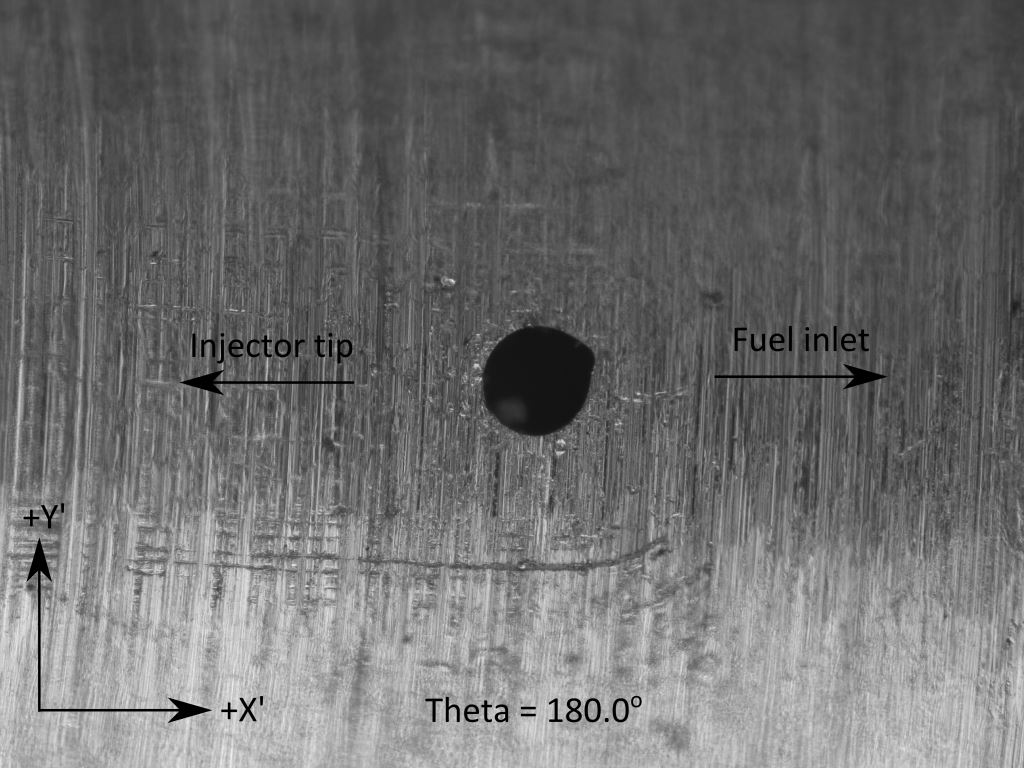
Microscopy exit diameter [μm] | Orifice exit picture | Orifice exit boundary .txt [μm] |
| 211196 | stl | H1:91.3; H2:91.5; H3:90.8 | H1 H2 H3 |
H1 H2 H3 |
| 211198 | stl | H1:92.0; H2:91.7; H3:91.5 | H1 H2 H3 |
H1 H2 H3 |
| 211199 | stl | H1:90.9; H2:91.7; H3:90.9 | H1 H2 H3 |
H1 H2 H3 |
| 211200 | – | H1:90.3; H2:90.3; H3:93.2 | H1 H2 H3 |
H1 H2 H3 |
| 211201 | see table below | H1:90.2; H2:91.5; H3:93.8 | H1 H2 H3 |
H1 H2 H3 |
| Injector Serial # | min. eff. diameter derived from ESRF stl [μm] use to compute flow coefficients |
effective flow area along hole axis |
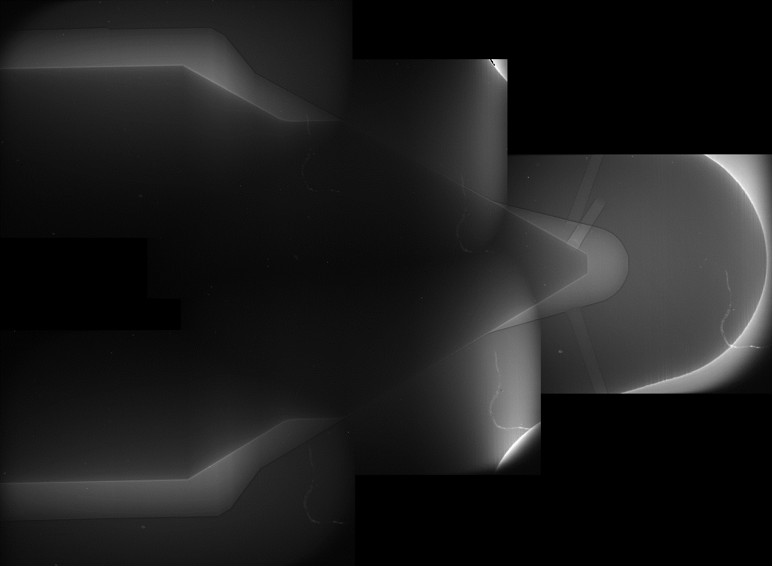
x-ray of needle and nozzle |
| 211201 | H1:91.0; H2:92.2; H3:95.8 | H1 H2 H3 |
phase-contrast image |
CDF meshes/geometry available for injector 211201
110 MBThis ESRF file is a compressed version of the previous and only contains the axial region of the nozzle containing the holes. Use the other “stl” file for needle and sac geometry as well as the x-ray image from Argonne for the upstream flow passage geometry.
| Stl file | Size | Description |
| Phoenix stl | 24.3 MB | Use this file for needle and sac geometry as well as the x-ray image from Argonne for the upstream flow passage geometry. |
| ESRF stl* | 3.4 GB | *Note injector 211201 “ESRF stl” has been chosen as the target Spray B injector geometry for internal flow simulations for ECN3. High-resolution x-ray tomography was performed at the European Synchrotron Radiation Facility by Peter Hutchins, Infineum Ltd.The stl file at this link is 3.4 GB, but this file has been downsized by Convergent Science to present a 110 MB alternative (listed below). |
| ESRF | 110 MB | This ESRF file is a compressed version of the previous and only contains the axial region of the nozzle containing the holes. Use the other “stl” file for needle and sac geometry as well as the x-ray image from Argonne for the upstream flow passage geometry. |
| CFD ready stl | 111 MB | Downsized ESRF file with inclusion of upstream fuel passages region of the nozzle exit. Provided by Argonne National Laboratories. Recommended for CFD. |
| CFD ready stl 2 | 32 MB | Smaller downsized ESRF file with inclusion of upstream fuel passages region of the nozzle exit. Provided by Argonne National Laboratories. Recommended for CFD. |
*Note injector 211201 “ESRF stl” has been chosen as the target Spray B injector geometry for internal flow simulations for ECN3. High-resolution x-ray tomography was performed at the European Synchrotron Radiation Facility by Peter Hutchins, Infineum Ltd. The stl file at this link is 3.4 GB, but this file has been downsized by Convergent Science to present a 110 MB alternative. Either ESRF file contains only the axial region of the nozzle containing the holes. Use the other “stl” file for needle and sac geometry as well as the x-ray image from Argonne for the upstream flow passage geometry.
Orifice exit boundaries (measured via optical microscopy) are provided in the table, but please note that these boundaries may NOT correspond to the orifice minimum despite the positive K factor for the orifice. Indications that this is the case are shown in the stl files and table.
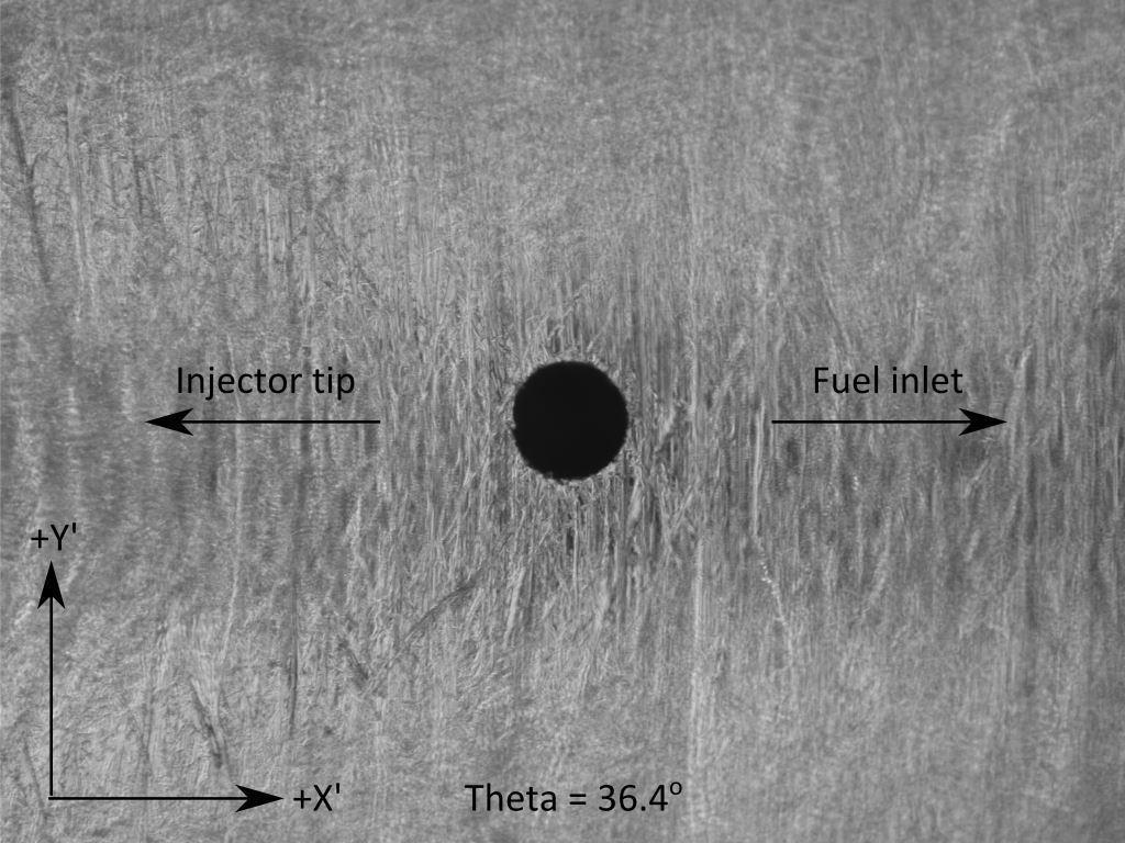
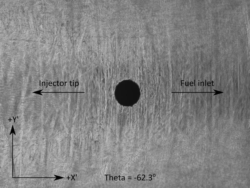
The microscopy-derived exit boundary is given as a text files (*.txt). Each hole has its own coordinate system (x’ and y’) in order to draw the hole exit boundary. The orientation of the particular coordinate system for the exit boundary imaging is shown in the orifice exit pictures, following is an additional description of the imaging process. Images were obtained orthogonal to the hole axis in order to focus on the exit boundary. Beginning with hole 3, the hole of interest, images were obtained with the very tip of the injector at the left and the injector body at the right. Keeping the optical system fixed, the injector was then rotated to bring the other holes into focus. As a result, the left of the image (-x’ direction) is always towards the tip of the injector (+x direction in Fig. 6.4.1).