Liquid penetration projected liquid volume map for nozzle 370 at Spray A conditions
The following is a reference dataset for Spray A liquid penetration using the preferred method for extinction diagnostics with diffused backlighting and sufficient illumination and collection, followed by post-processing for projected liquid volume using the optical setup and droplet diameter measurements from other work. Note that many other datasets for liquid penetration have been published for Spray A, including data found on ECN website, but this dataset uses an extinction imaging technique (rather than side Mie-scatter) that overcomes substantial beam-steering problems found in past data.
| Spray A serial # | 210370 |
| Amb. Temperature | 900 K |
| Amb. Oxygen | 0% |
| Injection Duration | 5.5 ms |
| Liquid penetration vs time (ensemble average) | EnsembleAverageLiquid |
| Projected liquid volume (PLV) threshold | 0.2e-3 mm^3 liquid / mm^2 |
| Quasi-steady liquid length (1-4 ms) for PLV threshold | 11.2 mm |
| PLV movie during 5.5 ms injection | PLV movie |
| Binary .mat file with PLV image data vs time | PLVdata |
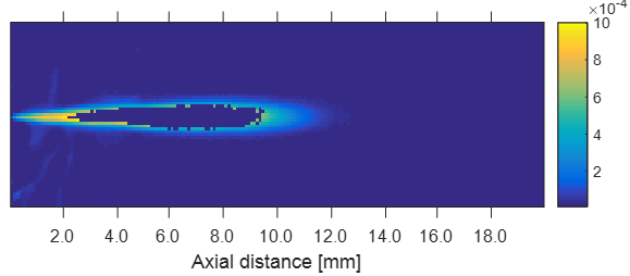
Quasi-steady projected liquid volume from 1 – 4 ms ASI. Regions of the fuel jet where optical thickness exceeded a value of 2 at any time during injection are excluded. Colorbar units in mm^3 liquid / mm^2
High-speed extinction imaging was applied with the optical setup described in the table below.
| Engineered diffuser full angle | 15 degree |
| Optical setup reference | DBI setup in Westlye 2017 |
| Wavelength of LED | 633 nm |
| Pixel resolution | 0.1064 mm / pix |
| Collection full angle | 146 mrad |
| Assumed droplet diameter | 0.0016 mm |
| Extinction cross-section | Cext = 4.08e-6 mm2 |
| Imaging speed | 120,000 frames per second |
The high-speed camera (Photron X2) was operated without shading correction to ensure that the background (zero photons) would be accurately measured. The extinction cross section considers the contribution of forward scatter light over the collection angle, but it does not consider forward-scatter sources. In optically thick regions, the extinction diagnostics is subjective to major errors, due to multiple-scattering as well as reflected light from vessel surfaces that may strike liquid droplets. Therefore, the data is sorted to identify optically thick regions with less than 12% transmission. The time resolved movie and binary datafile, returns NaNs at pixels with less than 12% transmission. The quasi-steady PLV average above indicates where NaNs were measured at an time during the quasi-steady period, indicating zones that could be biases by difficult measurements during injection.
Another error source for DBI extinction imaging is the coarse imaging size. Note that the spray with 0.090 mm nozzle diameter is under-resolved near the injector (< 2 mm) with pixel resolutions even larger than the nozzle diameter itself. The spray is optically thick in these regions (as measured by long-distance microscopy with high imaging resolution rather than that used in this setup) but high optical thicknesses (or PLV) are not measured because the spray overlaps only a part of an imaging pixel. Multiple imaging pixels are required to resolve these strong gradients. PLV is more accurately measured towards the liquid length itself downstream of approximately 8 mm where the optical thickness decreases, or at outer radial positions upstream in the fuel spray. However, concerns about adequate imaging pixel resolution at the radius of the jet apply because of the strong spatial gradient in the radial direction.