Overview
These experiments are performed in the single-cylinder optical research engine to characterize the effects of piston bowl geometry on flow, mixing, and combustion in the small-bore, swirl-supported diesel engine. Two piston geometries are compared with one another:
- A conventional, re-entrant piston bowl (conv) that is close to the production piston of the GM 1.9L engine (with valve cutouts for PIV measurements, no valve cutouts for all other experiments)
- A stepped-lip piston bowl (SL) that has been derived from the pistons employed in the Ford 6.7L Scorpion™ engine (no valve cutouts)

Spray targeting
The spray targeting in the engine (shown in the figure above) is adapted for each piston geometry based on recommendations from Ford and GM. This is achieved by changing the thickness of the copper sealing washer between the injector and the cylinder head. Spray targeting data are available in the file below:
Operating points and initial experimental findings
Initial scoping studies are performed with titanium pistons for injection timing sweeps for two types of operation:
- Conventional diesel combustion at part load (9 bar IMEPg) with a single pilot injection (constant pilot-main dwell); this operating point is referred to as CDC9
- Low-temperature combustion, part-load (3 bar IMEPg) with a single injection late in the compression stroke and a very dilute intake charge; this operating point is referred to as LTC3
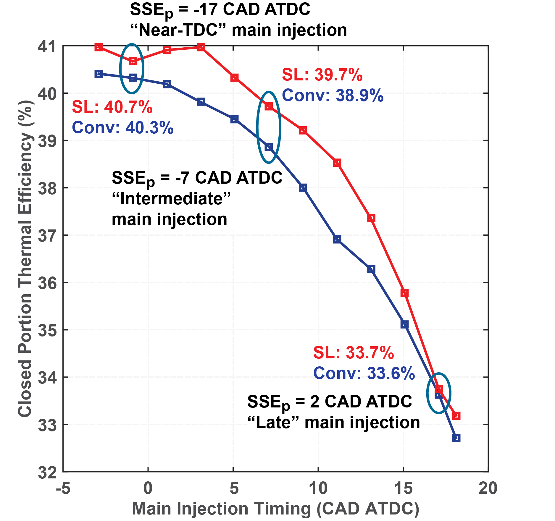
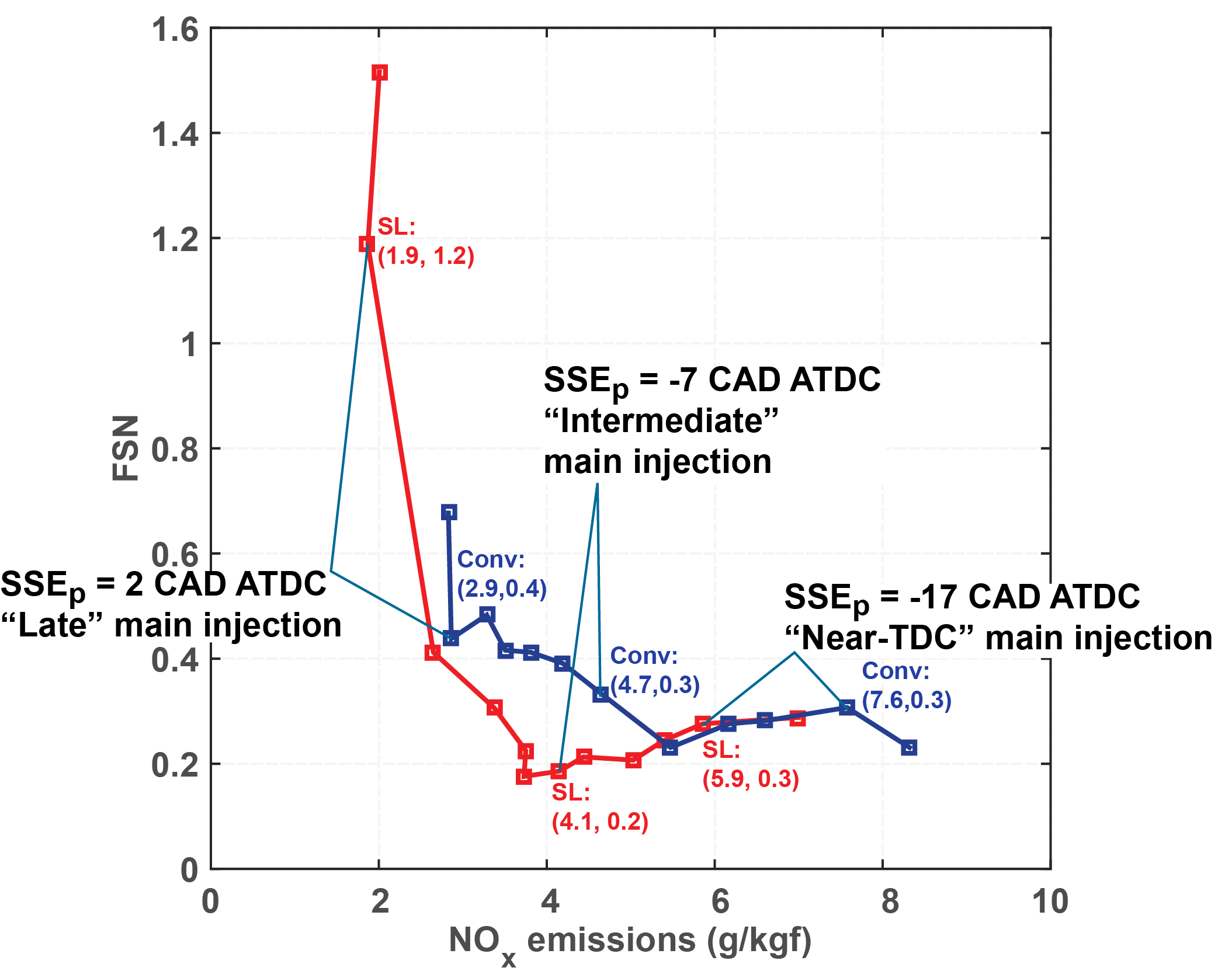
For each operating strategy, injection timing, and piston geometry, the main injection duration is adjusted to maintain a constant load. The results of these timing sweeps were used to determine the operating points for optical studies. For the CDC9 operating point, enhanced rates of mixing-controlled combustion are observed with the stepped-lip piston for main injections starting around 10 crank angle degrees after top dead center (CAD ATDC). For main injections starting near TDC or around 20 CAD ATDC, no significant enhancement is observed in mixing-controlled heat release rates. For this reason, three start-of-main-injection (SOImain) timings are studied with optical experiments for the CDC9 operating point, given as start of solenoid energizing for the pilot (SSEp) / SOImain:
- SSEp17b: SOImain = 0.9 CAD BTDC: near-TDC main injection; no significant difference in mixing-controlled heat release rates
- SSEp07b: SOImain = 9.1 CAD ATDC: intermediate injection timing; significant enhancement in mixing-controlled heat release rates with the stepped-lip bowl. Soot emissions are reduced by nearly 50% with the stepped-lip bowl.
- SSEp02a: SOImain = 18.1 CAD ATDC: late main injection; no significant difference in mixing-controlled heat release rates, but higher soot emissions with the stepped-lip bowl than with the conventional bowl.
Efficiency vs. Start of Main injection
Soot-NOx tradeoff
For the LTC3 operating point, piston geometry does not appear to have a significant impact on efficiency or emissions near the optimum injection timing (SOImain ~24 CAD BTDC). For injection timings before and after this, the combustion efficiency appears to deteriorate more rapidly for the conventional bowl than for the stepped-lip bowl. Three start of solenoid energizing (SSE) timings are chosen for study for the LTC3 operating point:
- SSE 36 CAD BTDC: for earlier injection timings, CO emissions increase and combustion efficiency decreases for both piston geometries. Combustion efficiency is higher for the stepped-lip piston than for the conventional piston.
- SSE 27 CAD BTDC: this is the optimum injection timing in terms of combustion efficiency and thermal efficiency for the conventional bowl geometry. Engine behavior is nearly the same with both bowl geometries.
- SSE 12 CAD BTDC: Combustion efficiency remains near its maximum value for both piston geometries, but thermal efficiency is improved with the stepped-lip bowl, possibly as a result of enhanced late-stage heat release rates.
Optical experiments
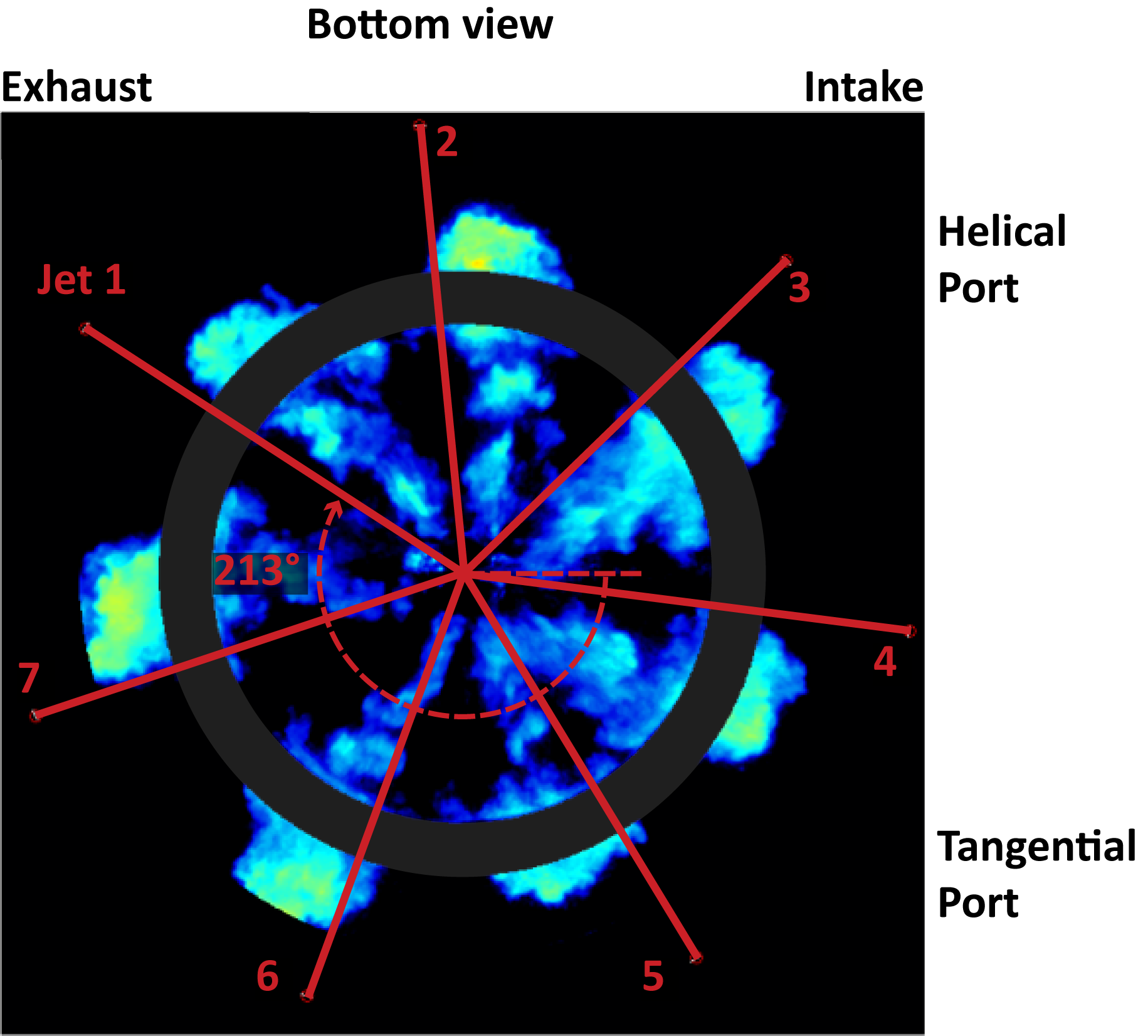
For the optical experiments, images are taken through the bottom of the transparent piston. The following experimental data are available for both piston geometries:
- Intake pressure, cylinder pressure, heat release rates, and estimated wall heat loss rates are available for each piston geometry, injection timing, and operating strategy. Both fired and motored cylinder pressure traces are available.
- Injection rate profiles for each piston geometry, injection timing, and operating strategy.
- For motored operation, planar particle image velocimetry measurements have been taken at various swirl-plane locations and at different crank angles and for different swirl ratio settings. Additionally, some data are available for a version of the conventional piston bowl geometry with valve cutouts.
- For the LTC3 operating point, high-speed Mie scattering images to show liquid fuel behavior and possible interactions with piston bowls.
- Quantitative, cycle-resolved, planar measurements of fuel concentration (fuel-air equivalence ratio) for both piston geometries at a range of crank angles and plane locations for each operating strategy.
- For the CDC9 operating point, combustion image velocimetry data: high-speed natural luminosity imaging is performed, and correlation techniques are applied to pairs of images to generate semi-quantitative velocity fields that represent the flow near the piston bowl surfaces. These data are intended to show the temporal development of flow patterns (particularly radial flow patterns) and how they are impacted by injection timing.
Injector clocking is as follows for these experiments:
Experimental Results
The data files are stored in the .zip files found below. Cylinder pressure-based and injection rate data are available in .xlsx files and should be self-explanatory. Imaging data are stored in binary .mat files (created with MATLAB R2014a). Additional explanations of the data contained in the mat files are available via the data file description documents contained within each .zip folder and/or subfolder. Details of each imaging experiment, including engine operation parameters and experiment settings are stored in .xlsx files in the folders containing each set of measurement results. Images are included that show:
- the experimental setup
- laser sheet locations, if applicable
- assumptions made when applying the ray tracing-based distortion correction algorithm
Cylinder pressure, injection rates, and heat release data
- Both piston geometries (no valve cutouts, equal squish height)
- Conventional diesel (pilot-main injection strategy) and LTC operation
- Three injection timings for each operating mode
- Combusting and non-combusting experiments
PIV
In-cylinder flow in various swirl planes; motored operation
- Conventional bowl: has valve cutouts and smaller squish height
- Stepped-lip bowl: no valve cutouts, larger squish height
- Three swirl ratios: 1.5, 2.2, 3.5 (Ricardo)
- Various swirl-planes (defined in filenames as distance below fire deck)
- Ensemble-average velocity fields (distortion corrected)
- For stepped-lip bowl, velocity fields are available for individual cycles
*Measurements and processing: Kan Zha
High-speed Mie scattering imaging
Time-resolved liquid fuel behavior: penetration and liquid spreading angle
- Non-combusting operation (N2 / CO2 instead of air)
- Flood illumination of cylinder contents with high-power, high pulse rate LED
- Imaging at 40 kfps
- Raytracing-based distortion correction
- Processed images available for individual cycles
- Background subtraction via the approximate median method (see Busch et al., 2014)
- Liquid length and liquid spreading angle computed for each cycle and each jet; available as ensemble average with standard deviation information
*Measurements and processing: Kan Zha
Fuel tracer PLIF
Cycle-resolved, quantitative fuel concentration images from various swirl planes
-
- Fuel doped with 0.5 wt% 1-methylnapthalene and excited with 266 nm horizontal laser sheet
- Temperature-dependent fluorescence signal -> iterative calculation of fuel concentration for each pixel
- Both piston geometries (no valve cutouts, equal squish height)
- Non-combusting experiments (O2 quenching prevents the technique from working)
- Data available for conventional and low-temperature operation
- Three different injection timings for each operating mode
- Three horizontal planes
- P1: halfway between fire deck and piston top
- P2 (conventional piston): bowl rim
- P2 (stepped-lip piston): slightly above piston top
- P3: deep in bowl
*Measurements and processing: Kan Zha
High-speed Natural luminosity and combustion image velocimetry (CIV)
Description of flow patterns near the piston bowl surface during mixing-controlled phase of combustion
- Both piston geometries (no valve cutouts, equal squish height)
- Conventional diesel operation; three different injection timings
- High-speed natural luminosity images used to derive information about flow during the mixing-controlled portion of the combustion event
- Individual cycle flow fields (as assumed to exist ~1 mm above the piston surface
*Measurements and processing: Kan Zha
References
Particle image velocimetry
Zha, K., Busch, S., Miles, P. C., Wijeyakulasuriya, S., Mitra, S. and Senecal, P. K., “Characterization of Flow Asymmetry During the Compression Stroke Using Swirl-Plane PIV in a Light-Duty Optical Diesel Engine with the Re-entrant Piston Bowl Geometry,” SAE Int. J. Engines 8(4):1837-1855, 2015, DOI: 10.4271/2015-01-1699
Zha, K., Busch, S., Park, C., Miles, P.C., “A novel method for correction of temporally- and spatially-variant optical distortion in planar particle image velocimetry,” Measurement Science and Technology, 27(8):085201, 2016
Mie Scattering
Busch, S., Zha, K., Miles, P.C., “Investigations of Closely Coupled Pilot and Main Injections as a Means to Reduce Combustion Noise,” presented at THIESEL 2014, Valencia, Spain, September 9-12, 2014.
Fuel tracer fluorescence technique
Sahoo, D., Miles, P. C., Trost, J. and Leipertz, A., “The Impact of Fuel Mass, Injection Pressure, Ambient Temperature, and Swirl Ratio on the Mixture Preparation of a Pilot Injection,” SAE Int. J. Engines 6(3):1716-1730, 2013, DOI: 10.4271/2013-24-0061
High-Speed Natural Luminosity Imaging / CIV
Zha, K., Busch, S., Warey, A., Peterson, R. C. and Kurtz, E., “A Study of Piston Geometry Effects on Late-Stage Combustion in a Light-Duty Optical Diesel Engine Using Combustion Image Velocimetry,” SAE Technical Paper 2018-01-0230, 2018
Injection Rate Profiles
Busch, S. and Miles, P. C., “Parametric Study of Injection Rates With Solenoid Injectors in an Injection Quantity and Rate Measuring Device,” Journal of Engineering for Gas Turbines and Power, 137(10):101503-101503, 2015, DOI: 10.1115/1.4030095
Thermodynamic / CFD-based Analyses
Busch, S., Zha, K., Kurtz, E., Warey, A. and Peterson, R., “Experimental and Numerical Studies of Bowl Geometry Impacts on Thermal Efficiency in a Light-Duty Diesel Engine.” SAE Technical Paper 2018-01-0228, 2018, DOI: https://doi.org/10.4271/2018-01-0228.
Busch, S., Zha, K., Perini, F., Reitz, R., Kurtz, E., Warey, A. and Peterson, R., “Bowl Geometry Effects on Turbulent Flow Structure in a Direct Injection Diesel Engine.” SAE Technical Paper 2018-01-1794, 2018, DOI: https://doi.org/10.4271/2018-01-1794.