Penetration and Combustion Characterization of Cavitating and Non-Cavitating Fuel Injectors under Diesel Engine Conditions (SAE 2016 World Congress and Exhibition, DOI for Paper)
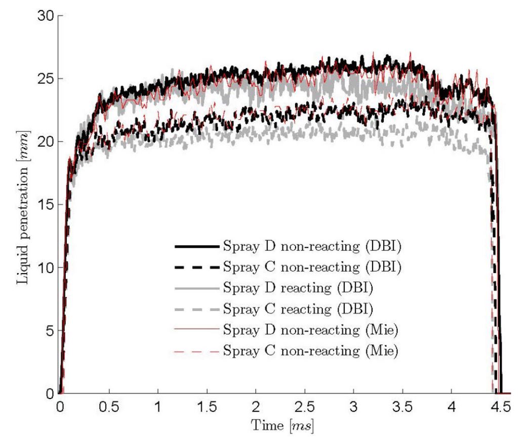
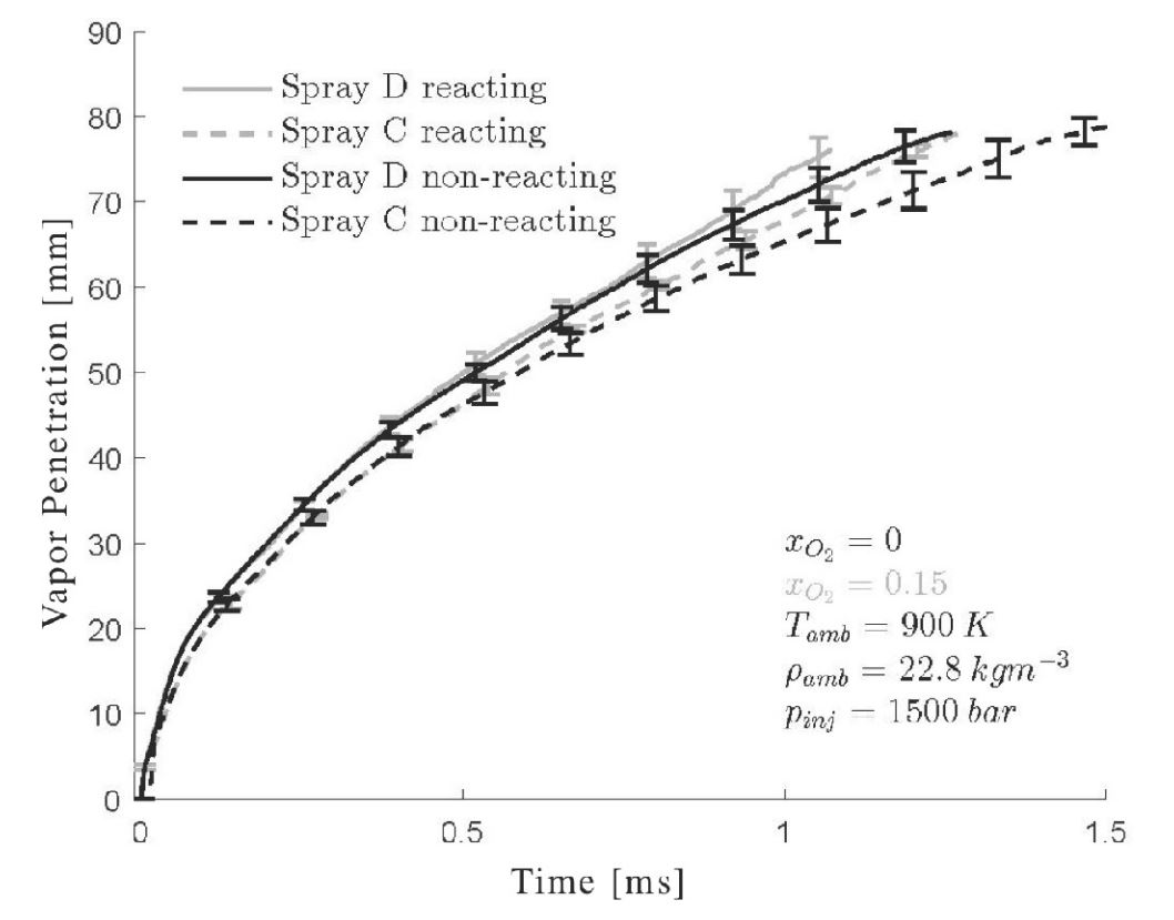
This work investigates the effects of cavitation on spray characteristics by comparing measurements of liquid and vapor penetration as well as ignition delay and lift-off length. A smoothed-inlet, converging nozzle (nominal KS1.5) was compared to a sharp-edged nozzle (nominal K0) in a constant-volume combustion vessel under thermodynamic conditions consistent with modern compression ignition engines. Within the near-nozzle region, the K0 nozzle displayed larger radial dispersion of the liquid as compared to the KS1.5 nozzle, and shorter axial liquid penetration. Moving downstream, the KS1.5 jet growth rate increased, eventually reaching a growth rate similar to the K0 nozzle while maintaining a smaller radial width. The increasing spreading angle in the far field creates a virtual origin, or mixing offset, several millimeters downstream for the KS1.5 nozzle. Remarkably, this mixing offset appeared to globally influence the liquid penetration and lift-off stabilization location over a wide range of operating conditions. When this offset was removed, OH chemiluminescence-derived lift-off lengths for the two nozzles essentially collapsed. An Eulerian multiphase mixture model, with Large-Eddy Simulations (LES) combining internal and external flow predicted the trends in spreading angle in the region close to the injector. The K0 simulation showed cavitation zones along walls downstream of the nozzle inlet with some dispersion into the center of the jet before the nozzle exit. With a slightly diverging nozzle (as measured), the K0 simulation also indicated that low pressure zones draw ambient gas just inside the nozzle exit, which, combined with cavitation dynamics, should be considered as a potential contributor to the initial growth rate.
Experimental Setup:
The experimental installation used to generate diesel engine environments in which to inject liquid fuel is detailed in Siebers’ “Liquid-Phase Fuel Penetration in Diesel Sprays”. Only key features of the installation will be mentioned here and more attention will be given to the optical arrangement.
Combustion Vessel and Injection System
In this constant-volume (CV) combustion vessel, a combustible mixture of gases is ignited in order to reach the desired thermodynamic state in which to inject the liquid fuel spray. The composition of the combustible gas can be modified to generate a range of oxygen concentrations from simulated air to an inert environment (no oxygen). The premixed combustion event increases the pressure and temperature and the injection is initiated after a relatively long cool-down period where the target conditions are met. The injected fuel was spectrophotometric grade n-dodecane and represents one of the standard fuels used in the ECN.
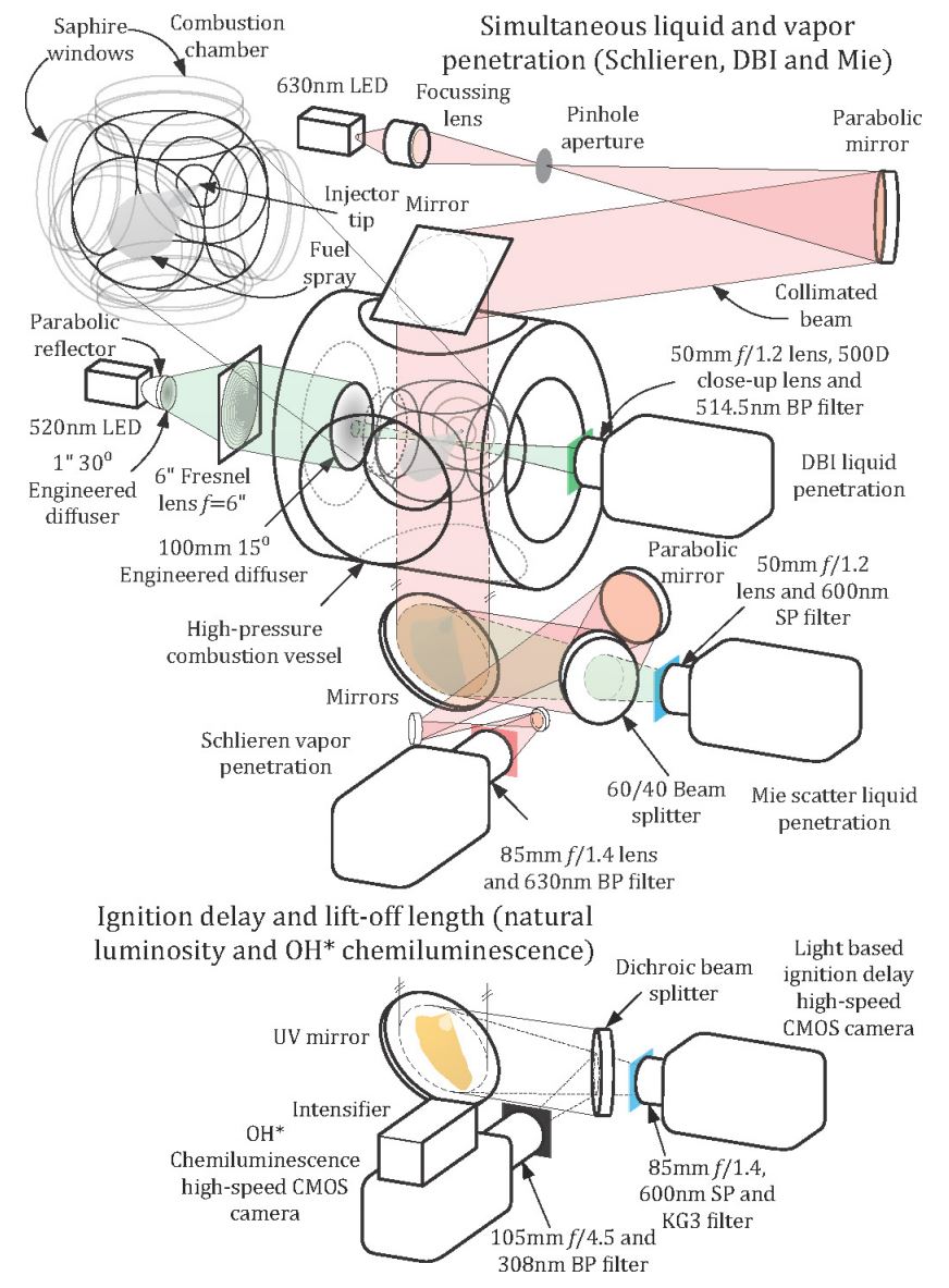
Simultaneous Liquid and Vapor Penetration
The vessel was configured with dual line-of-sight optical access, which was exploited in order to collect measurements of the liquid and vapor phase simultaneously using two back-illumination diagnostics with different lighting requirements. Two optical techniques were used simultaneously to monitor liquid phase penetration: Mie scatter and diffused back-illumination (DBI) imaging. Beyond the tip of the liquid-phase of the spray, the fuel vaporized and mixed with the entrained ambient gas. The jet boundary was imaged via schlieren imaging visualizing density gradients between the jet and ambient. The DBI and schlieren light sources were spectrally separated and the cameras were equipped with appropriate filtering to prevent interference among the two diagnostics.
Lift-Off Length and Ignition Delay
The lift-off length describes the distance between the injector outlet and the spatial location of high temperature reactions. Direct line-of-sight imaging of OH* chemiluminescence was used to track ignition site and flame stabilization position. The ignition delay depicts the time from the start of injection to the time when high-temperature ignition was first observed. An intensity threshold was used to determine the ignition delay and the spatial location of ignition. The specifics of the optical arrangement can be seen in the experiment setup graphic above.
Data:
Data Links:
| Liquid/Vapor | Link to Download |
|---|---|
| Liquid | bkldc_liq.mat |
| Liquid | bkldd_liq.mat |
| Liquid | SprayC_liquid.mat |
| Liquid | SprayC_liquid.txt |
| Liquid | SprayD_liquid.mat |
| Liquid | SprayD_liquid.txt |
| Vapor | SprayC_vapPen.mat |
| Vapor | SprayC_vapPen.txt |
| Vapor | SprayD_vapPen.mat |
| Vapor | SprayD_vapPen.txt |